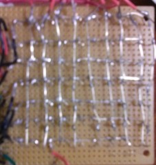
This project uses the MSGEQ7 in order to power a 7 channel LED equalizer. The goal was to use current components that were already avilable. Using 70 LEDs, a 7×10 matrix was created by soldering the anodes in each row together and the cathodes in each column together. The matrix setup can be seen in Figure 1 below.

Figure 1 – Back of LED matrix
Some 16 channel multiplexers (cd74hc4067e) were laying around so they were used to light a certain column and row at the same time making one LED light up at a time. The datasheet can be found . The common input was tied to 5v or ground. The MSGEQ7 was used to separate the audio signal into 7 channels. Since the average audio range for a human is 20Hz-20kHz, the IC separates the singal by 63Hz, 160Hz, 400Hz, 1kHz, 2.5kHz, 6.25kHz and 16kHz. These seven signals are 5V logic and it’s voltage value is dependent on the volume of the signal. The datasheet contains the components necessary to use the chip and can be found . The ATmega328P with the Arduino bootloader and a 16MHz crystal oscillator was use to program the LED matrix. All of this was powered by a 5V regulator. The finished prototype is shown in the video below.
int analogPin = 0; // pin for msgeq7 input
int strobePin = 13; // msgeq7 strobe pin for cycling through channels
int resetPin = 12; // reset pin of the msgeq7
int spectrumValue = 0; // current spectrum value
int highLowDelay = 0; // delay of resetting msgeq7
int strobeDelay_USec = 15; // delay to settle input recording in microseconds
int numberOfChannels = 7; // number of channels in
int divider = 100;
int multiplier = 1;

int multiBlack[4] = {2,3,4,5};
int multiRed[4] = {6,7,8,9};

int muxChannel[9][4]={
    {0,0,0,0}, //channel 0
    {1,0,0,0}, //channel 1
    {0,1,0,0}, //channel 2
    {1,1,0,0}, //channel 3
    {0,0,1,0}, //channel 4
    {1,0,1,0}, //channel 5
    {0,1,1,0}, //channel 6
    {1,1,1,0}, //channel 7
    {0,0,0,1}, //channel 8
  };

/*------------------------------------------------------------
Setup Method.  Initializes all pins
------------------------------------------------------------*/
void setup() {
 // open usb serial port
 Serial.begin(9600);

 // turn on pins for msgeq7
 pinMode(analogPin, INPUT);
 pinMode(strobePin, OUTPUT);
 pinMode(resetPin, OUTPUT);

 for(int i=0;i<8;i++) {
   pinMode(i+2,OUTPUT);
 }

 analogReference(DEFAULT);

 // reset msgeq7
 digitalWrite(resetPin, LOW);
 digitalWrite(strobePin, HIGH);
} // void setup()

/*------------------------------------------------------------
Loop method. Resets msgeq7 and captures value of the
7 channels on the msgeq7.
------------------------------------------------------------*/
void loop()
{
 digitalWrite(resetPin, HIGH);
 delay(highLowDelay);
 digitalWrite(resetPin, LOW);

 for (int i=0; i<numberOfChannels;i++) {
   // start reading channel by changing strobe to low
   digitalWrite(strobePin, LOW);
   // allows input to settle to get accurate reading
   delayMicroseconds(strobeDelay_USec);
   // read value of current pin from msgeq7
   spectrumValue = analogRead(analogPin);

   // print out value to serial monitor
   Serial.print(spectrumValue);
   Serial.print(" ");

   for(int j=0;j<4;j++) {
     digitalWrite(multiBlack[j], muxChannel[i][j]);
   } // for(int j=0;j<4;j++)

   for(int n=1+multiplier;n<10+multiplier;n++) {
     for(int k=0;k<n-multiplier;k++) {
       if(spectrumValue > divider*n) {
         for(int m=0;m<4;m++) {
           digitalWrite(multiRed[m], muxChannel[k][m]);
         } // for(int m=0;m<4;m++)u
       } // if(spectrumValue[i] > 30*n)
     } // for(int k=0;k<n;k++)
   } // for(int n=1;n<10;n++)

  // strobe pin high the low to go to next channel on msgeq7
   digitalWrite(strobePin, HIGH);

 } // for (int i = 0; i < numberOfChannels; i++)
 Serial.println();

} // void loop()